
P1 · P2
Type K/J thermocouples.
Temperature on the line or on critical surfaces, at process points that need a wider range.
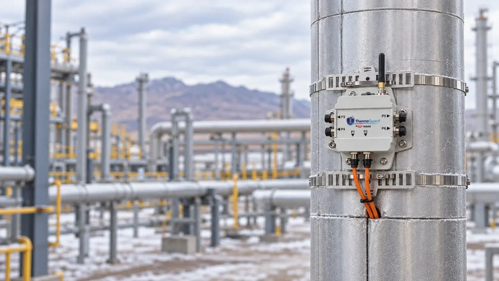
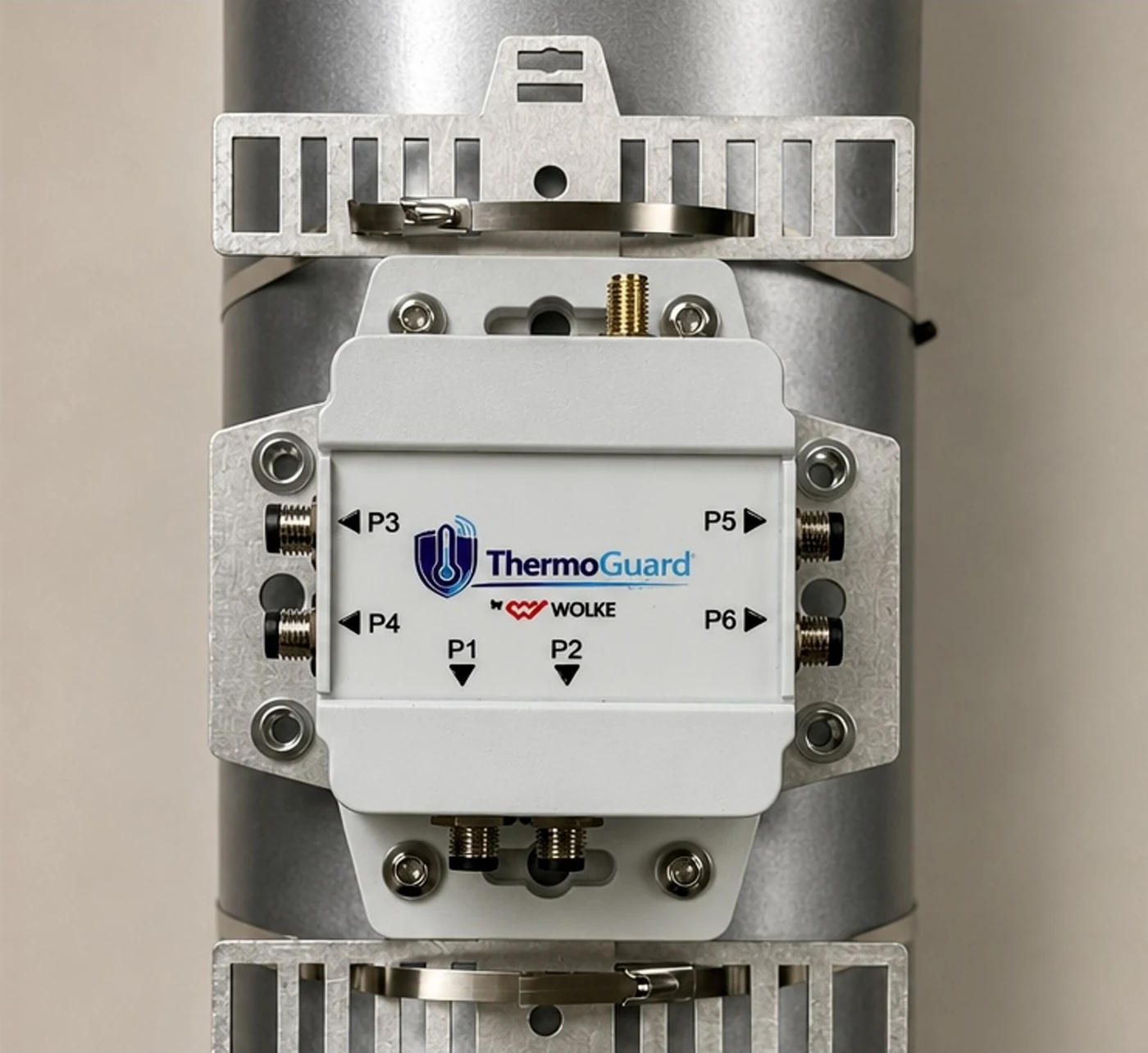
ThermoGuard is our wireless IP68 node that measures temperature, humidity, current, and status signals right at the asset.
It installs without running cable or stopping the process, transmits over BLE to VigiaBOX, and turns amps and degrees into conditions your operations team understands.
The plant is instrumented, but many auxiliary systems are still blind spots. The control system reports the command; in the field, something else may be happening.
| Auxiliary system | What the control system reports | What's happening in the field |
|---|---|---|
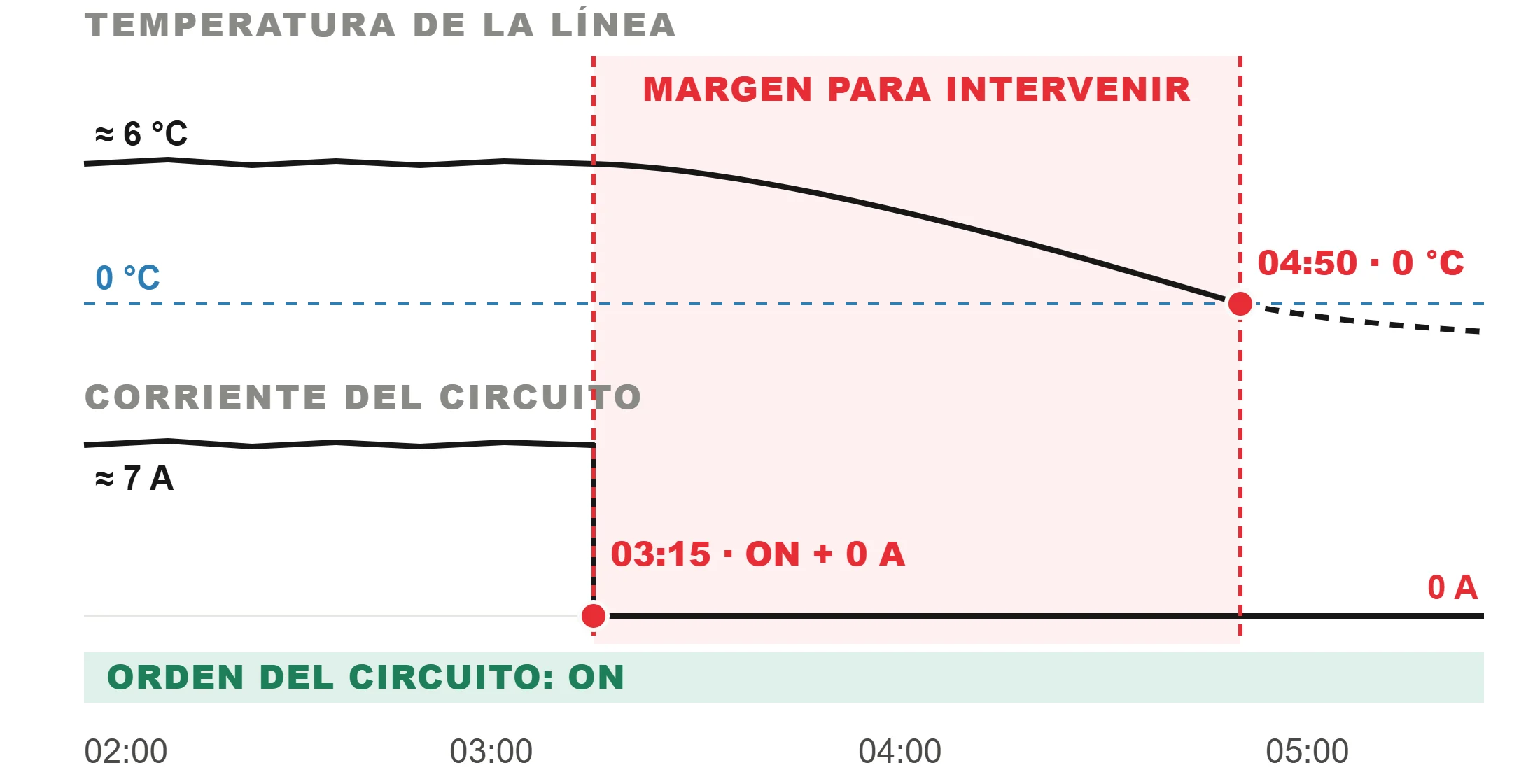
| Heat tracing | Circuit energized | Normal current, no temperature response |
| Room ventilation | Command ON | Exhaust fan drawing no current: 0.0 A |
| Line insulation | No signal | Abnormal moisture under the insulation |
Status, current draw, thermal response, and ambient conditions, measured right at the asset. The same hardware adapts to each load with a different profile.
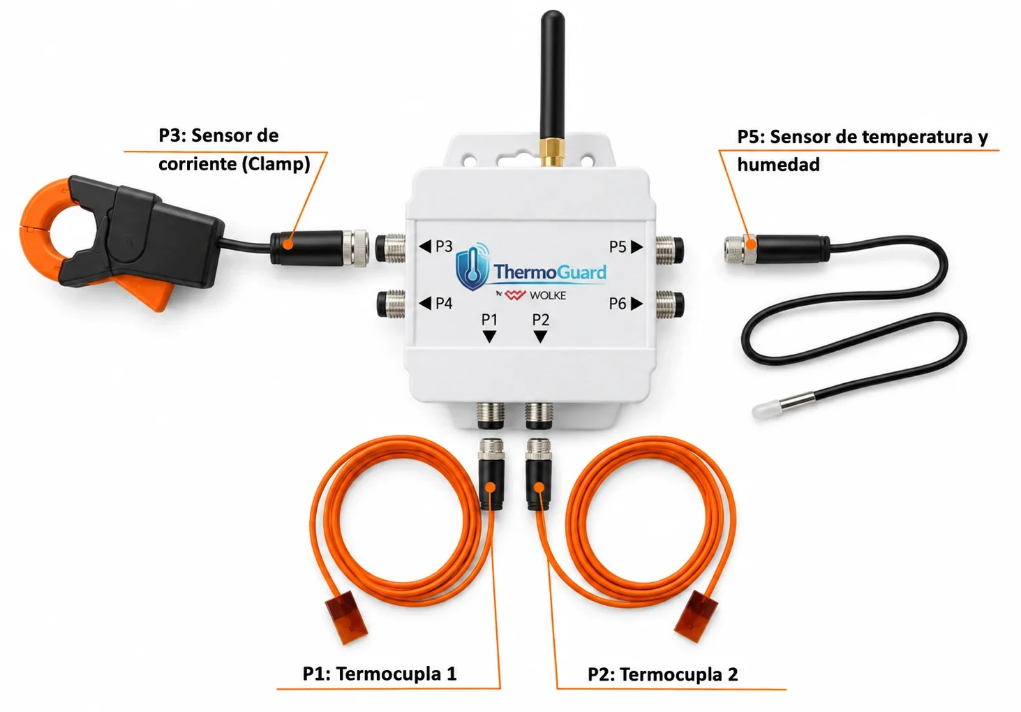
Temperature on the line or on critical surfaces, at process points that need a wider range.
Non-invasive CT clamp that measures RMS current without breaking or modifying the circuit.
Ambient or under the insulation, to catch abnormal moisture early.
10K NTC thermistor, low-voltage analog, or dry contact for run and fault status. In the thermal profile, one node handles up to 6 temperature and 2 humidity channels.
ThermoGuard cross-checks what should be happening against what is actually happening. VigiaBOX applies the rules at the edge, and every alarm arrives with the reason behind it.
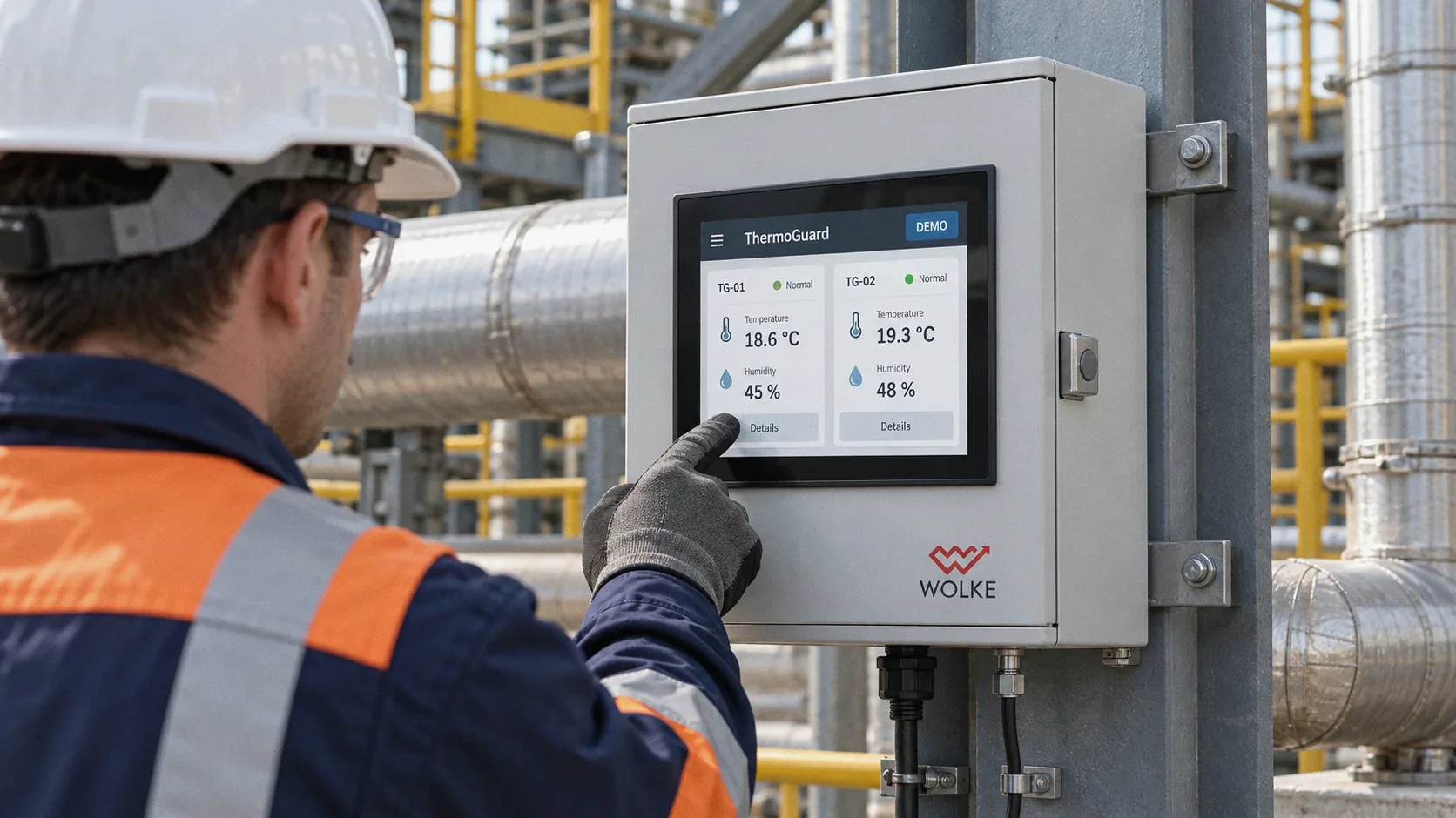
ThermoGuard measures right at the asset. VigiaBOX gathers the data from each zone, buffers the history through outages, and delivers it to the local HMI, the web platform, or your systems. Primary protection stays with the local equipment, the PLC, or the SIS.
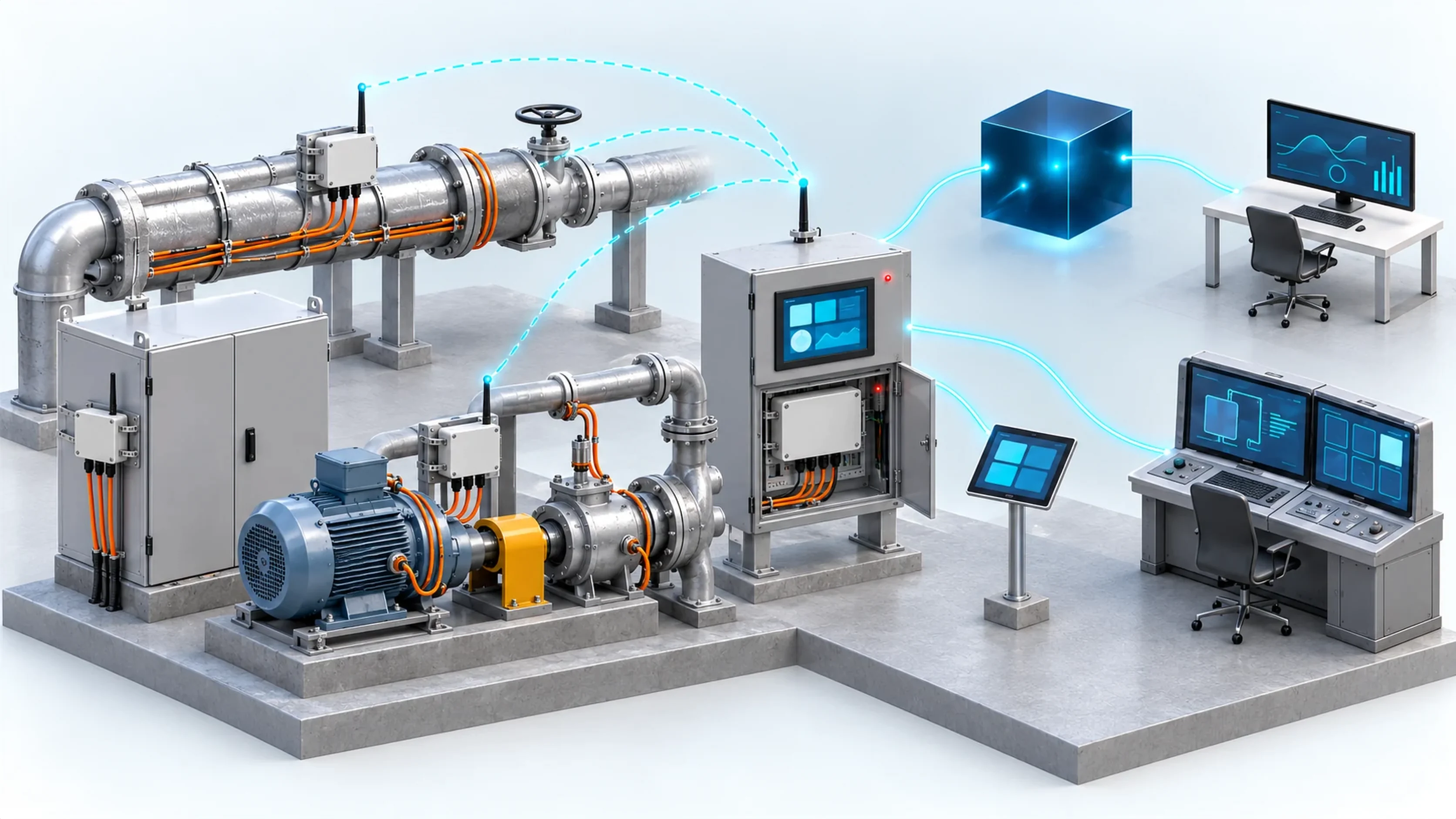
Assets with ThermoGuard
BLE · up to 50 m
Zone VigiaBOX
Local HMI
Web platform
Your systems
Assets with ThermoGuard
Heat-traced lines, panels, motors, and pumps, with a node next to each asset.
BLE · up to 50 m
No field wiring: each node transmits to its zone gateway.
Zone VigiaBOX
Edge rules, power backup, and a local buffer during outages.
Local HMI
10" screen in the enclosure to run the zone even if the link drops.
Web platform
Supervision by plant, area, and asset, with every event in context.
Your systems
SCADA or your cloud, over API or MQTT.

We do not turn VigiaBOX into a PLC: we check that simple electrical loads are available and respond as they should. The heat tracing application is already running in the field; other loads are added on a per-project basis.
Current, line temperature, and humidity under the insulation, circuit by circuit.
Field-provenCabinet heater, ventilation, temperature, humidity, and auxiliary power.
Motor stopped, heater required, and actual heater current.
Current, heat-up time, and target temperature.
Run, fault, current, and cycles for each unit.
Status, backup, and condition of the auxiliary power.
ThermoGuard already runs on heat-traced lines at a gold and silver mine in the high Andes of northern Chile.
RokkaGuard is our monitoring solution for auxiliary systems, built on ThermoGuard and VigiaBOX. It starts with one critical circuit and reuses the same infrastructure at every stage.
ThermoGuard nodes on each circuit and a VigiaBOX with HMI in each zone.
Field-provenHeaters, panels, sumps, and UPS units on the same zone VigiaBOX.
Project-basedExisting certified detectors over Modbus or 4–20 mA. Primary safety stays intact.
Project-basedBLE tags for people and assets: presence and last known zone with every event.
Project-based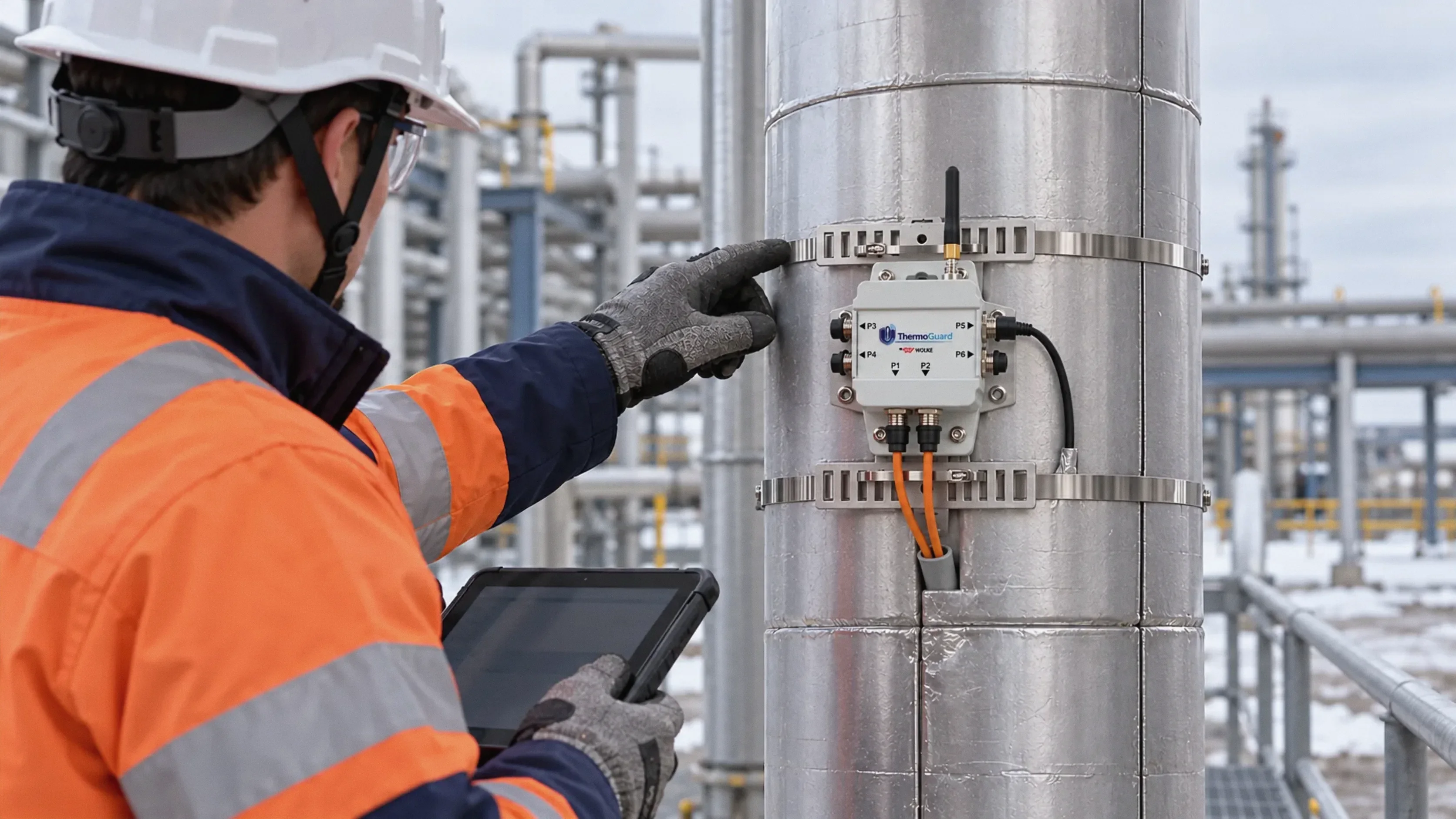
Profiles, thresholds, and scope are defined with each plant, on the same hardware.
| Device type | Wireless measurement node installed at the asset |
|---|---|
| Inputs | Type K/J thermocouples, 10K NTC thermistor, temperature/humidity sensor, CT current clamp (RMS), low-voltage analog, and dry contact |
| Typical configuration | Up to 6 temperature and 2 humidity channels per node, or profiles with current and status signals |
| Communications | BLE to VigiaBOX, up to 50 m line of sight; signal strength reported per antenna |
| Setup | ThermoGuard Android app, over BLE |
| Protection | IP68, weather-sealed |
| Operating temperature | −30 to 50 °C |
| Power | Internal battery; runtime depends on measurement frequency |
| Gateway | Zone VigiaBOX with 10" local HMI, backup power, and local buffer; 4G, LoRaWAN, or satellite |
| Integration | Local HMI, web platform, API, MQTT, or SCADA, through the zone VigiaBOX |
| Installation | Pipe-mounted bracket with metal clamps; thermocouples secured with aluminum tape; humidity sensor inside the insulation. No field wiring, no process shutdown |
No. Primary protection stays with the local equipment, the PLC, or the SIS. ThermoGuard adds visibility, context, and history.
No. Each node transmits over BLE to its zone's VigiaBOX. Only the gateway needs power.
VigiaBOX has backup power and keeps the history locally, resending it when the link returns.
Yes. VigiaBOX accepts 4–20 mA, Modbus, and digital inputs, including certified third-party detectors.
Heat tracing, panels, motors, pumps, or heaters: tell us which auxiliary system you can only see as energized today.